Engineering first. Curiosity always.Copenhagen / Open to opportunities
↖ Back to selected work

Engineering & Innovation04 / 08

DTU / Mechanical CAD / 2024

Vintage
Banker’s Lamp.

A familiar object, rebuilt one component at a time.

Year
2024
My role
Collaborative CAD development
Shared project work
Tools & methods
PTC Creo · Autodesk 3ds Max
Component modelling · Assembly · Materials · Rendering
Context
Mechanical CAD · DTU
CAD Modeling & Product Visualization
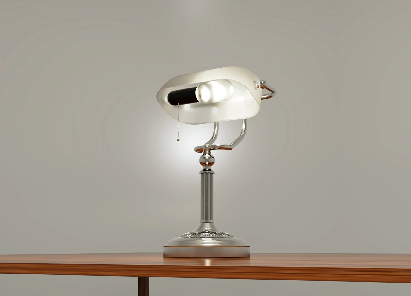
Final rendering of a metallic vintage banker’s lamp with a glowing white glass shade on a wooden table
Final visualization / Autodesk 3ds Max

01 / Reference & proportions

Start with
the real object.

A collaborative CAD study recreating a vintage banker’s lamp.

Reference photographs and published dimensions established the proportions before the lamp was broken down into individual components. The work balanced a simple overall silhouette with decorative details and curved surfaces.

The reference indicated a 39 cm overall height and a 28 cm shade width. These informed the reconstruction; they are reference dimensions, not verified CAD tolerances.
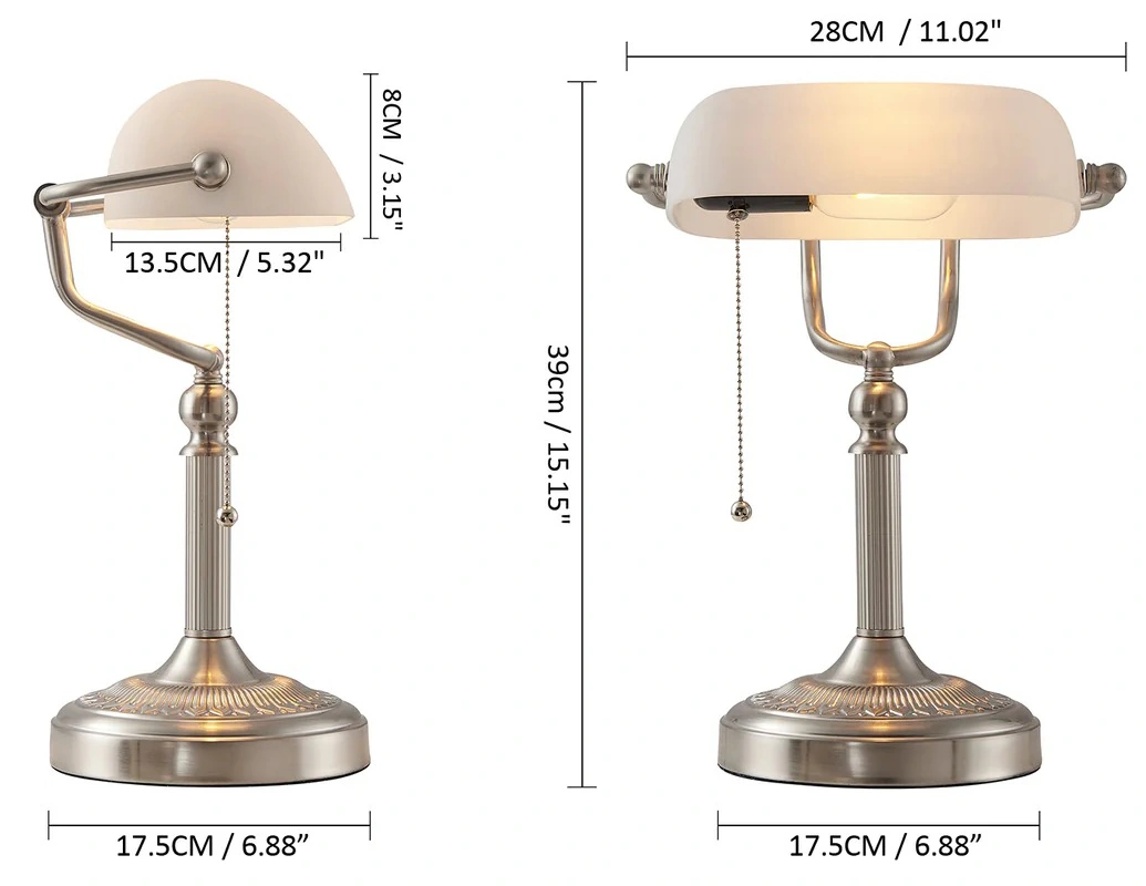
Dimensioned research photograph showing the reference lamp’s height, shade and base proportions
Research reference / dimensions used to guide the reconstruction
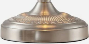
Supplied reference photograph of the vintage lamp’s metallic decorative base
Reference detail / the base
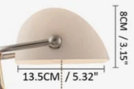
Supplied side reference of the lamp shade labelled 13.5 centimetres deep and 8 centimetres high
Reference detail / shade proportions

02 / Component development

Profiles.
Features.
Repetition.

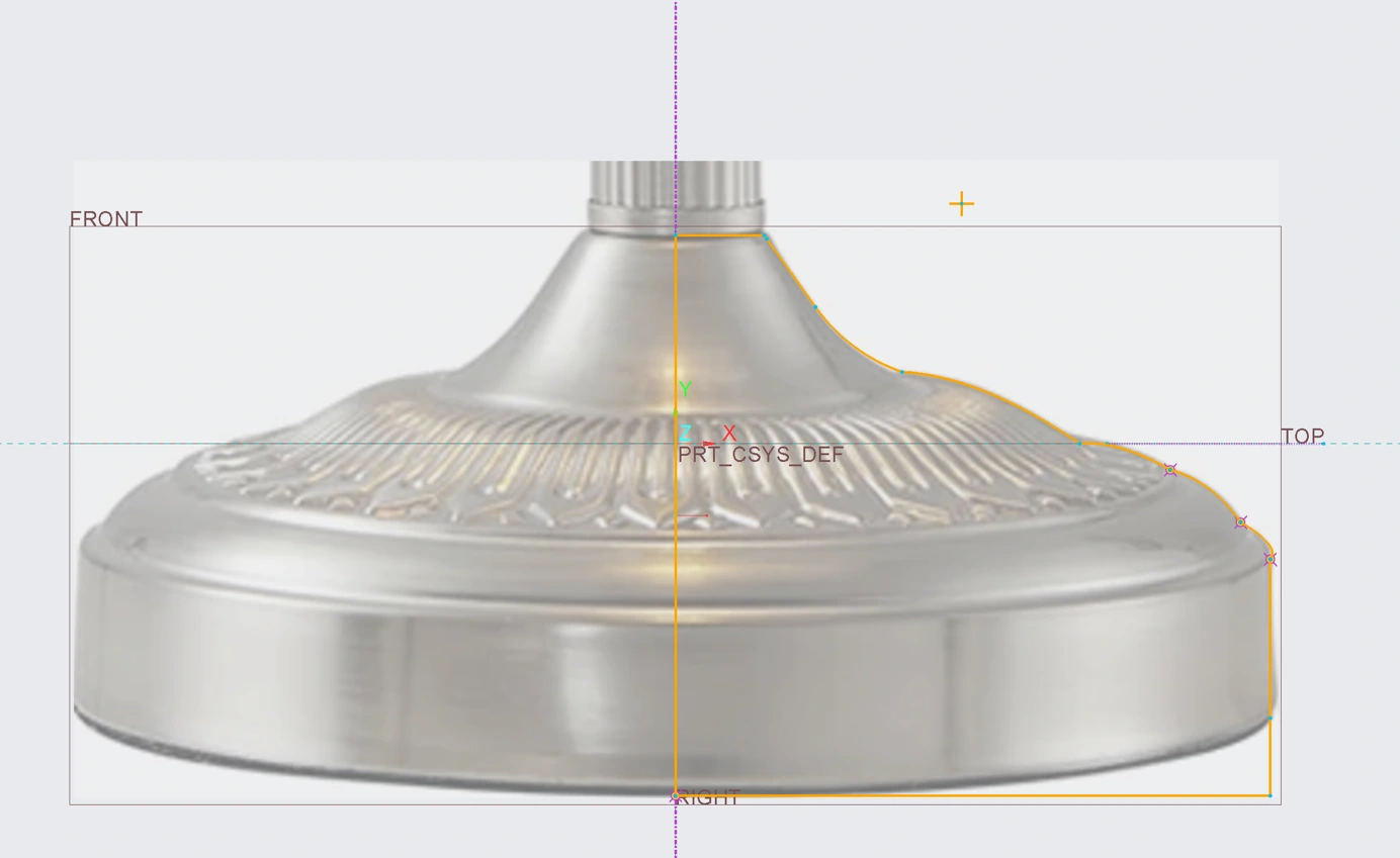
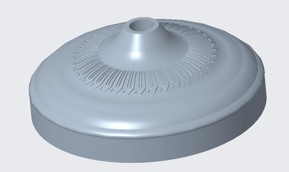
A revolved reference profile established the base. Extrude shaped the ornament, then rounding and a 36-instance Pattern repeated the detail around the surface.

Feature order mattered: rounding the original feature before patterning it avoided individually refining every copy.

Creo sketch of the lamp base profile traced from a reference photograph
Base / reference profile before Revolve
The modelled lamp base with repeated decorative details
Base / rounded detail repeated with Pattern

03 / Supporting structure

Follow the curve.

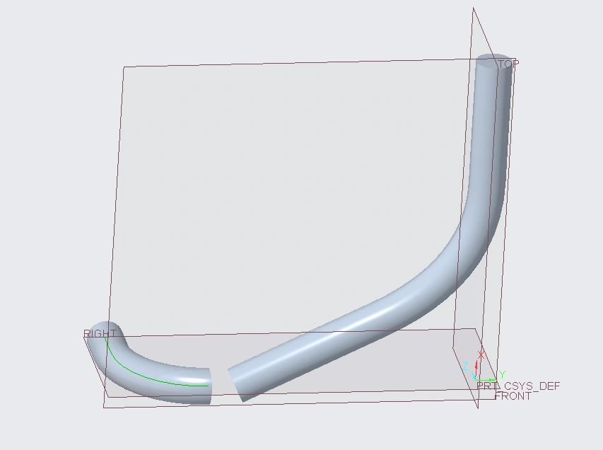
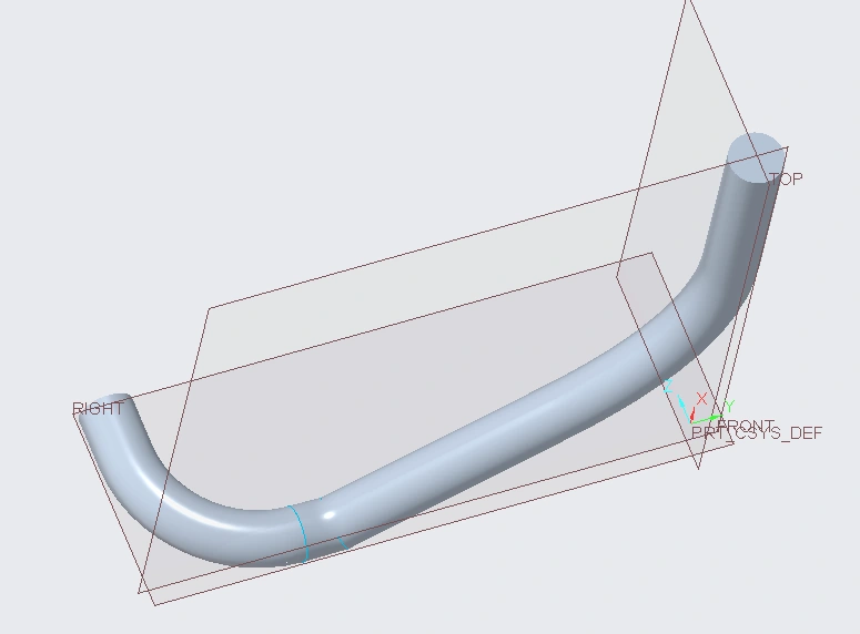
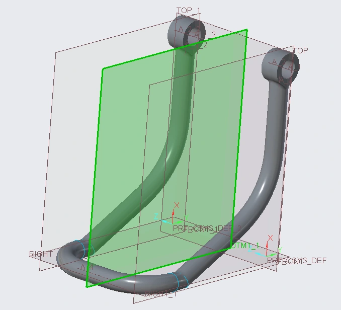
Sweeps formed the curved supporting arms. A Blend joined pipe segments running in different directions; mirroring completed the paired structure.

Separate swept pipe segments in the Creo support-arm model
Sweep / establish the curved paths
Blend transition connecting the swept pipe segments
Blend / connect the segments
Mirrored supporting arms around an offset datum plane
Mirror / complete the paired structure

04 / Surface modelling

The shade
set the challenge.

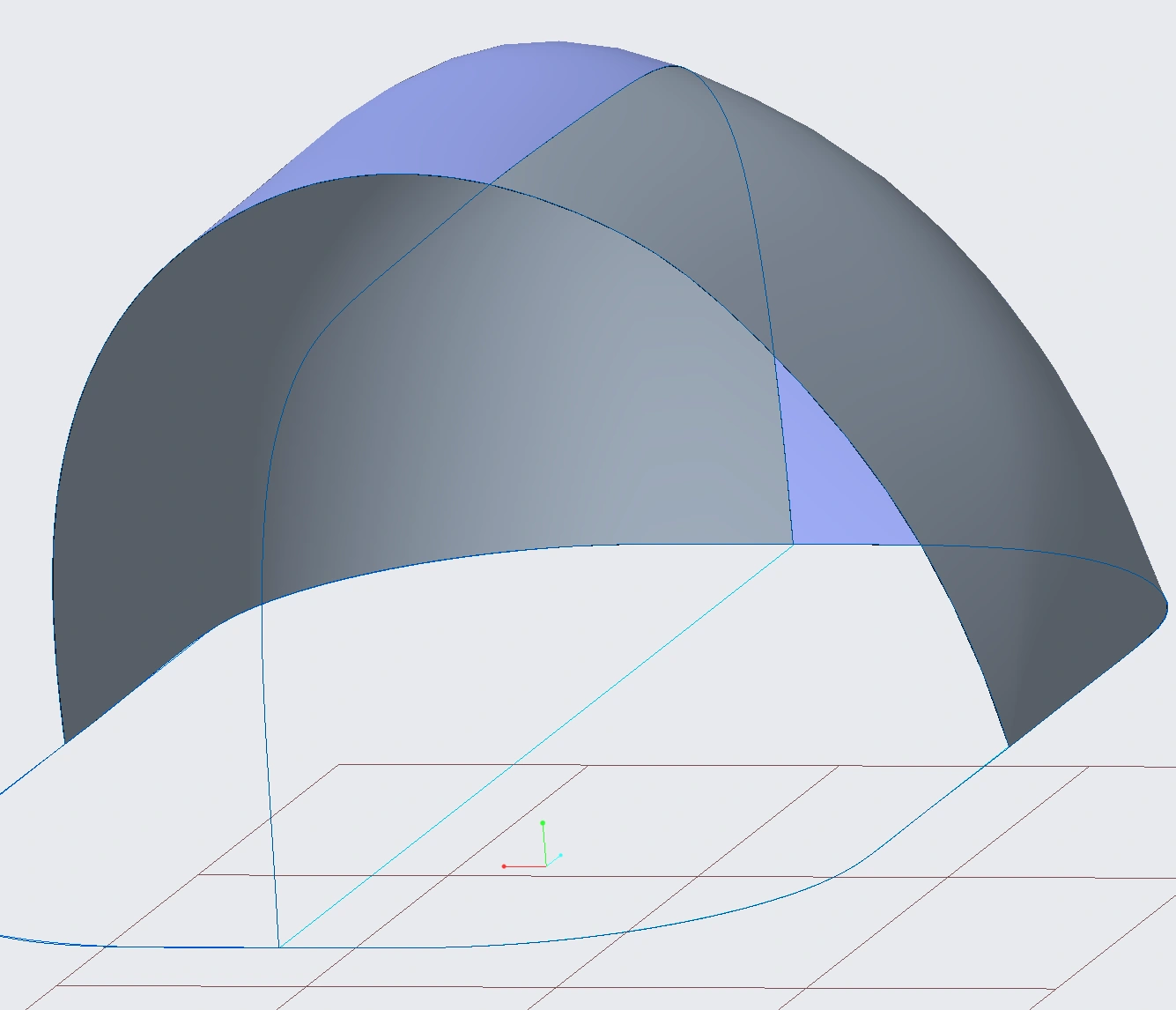
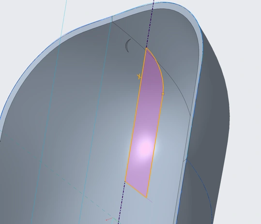
The lampshade began with curves in Style. A surface was created, mirrored and thickened, then developed with mounting details and an internal bulb holder.

A controlled-fit Thicken operation removed a groove at the midpoint. A separate outward bulge remained on the shade’s sides, showing how strongly the final surface depended on the initial curves and reference alignment.

The curved lampshade surface being developed in Creo using Style curves
Shade / curves, surface, symmetry and thickness
The modelled internal bulb holder beneath the lampshade
Internal assembly / Revolve and Shell for the bulb holder

05 / Assembly

From parts
to one object.

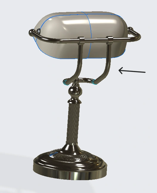
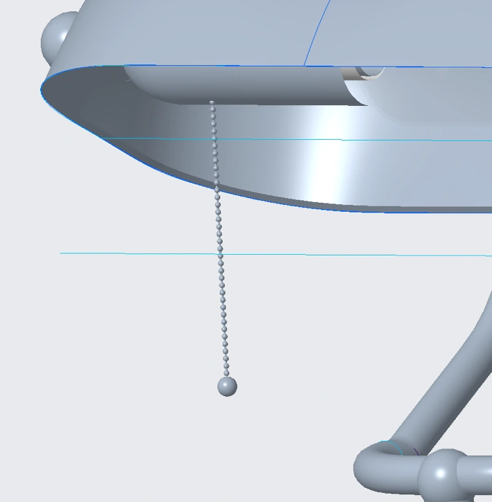
The components were assembled in Creo, including the base, stem, supporting arms, shade, bulb and pull cord. Connections and cord geometry were adjusted to produce a more natural assembly.

The complete model was then exported to Autodesk 3ds Max for the final visualization.

Complete Creo lamp model shown in the report to locate the first supporting arm
Complete CAD model / source annotation identifies a supporting arm
The pull cord positioned beneath the shade in the CAD assembly
Detail / adjusting the pull cord for a natural drop

06 / Materials, light & reflection

Rendering makes
geometry visible.

A metallic finish was applied to the base and arms, with white opalized glass for the shade and integrated lighting in 3ds Max.

The render brought the components together while revealing remaining surface imperfections. The key lesson was to check symmetry, continuity and feature order early — before detail and rendering make changes more expensive.

This was a digital reconstruction and visualization study. It did not include manufacture, structural testing or tolerance verification.

Complete final rendering of the illuminated banker’s lamp, preserving the original proportions
Final result / original rendering extracted from report page 19

Keep exploring / Sustainable product development

OceanPlate

Let’s talk about your next project ↗
Enlarged project image